


5 inch CAN Bus TFT Display with Projected Capacitive Touch
Model No. WL0F00050000FGAAASA00
We have three demo scenario as below.
WL0F00050000FGAAASB00 (Industrial Application)
WL0F00050000FGAAASC00 (Vehicle Application)
WL0F00050000FGAAASD00 (Medical Application)
►TFT Size: 5"
►TFT Resolution: 800×480 dots
►TFT View Direction: IPS
►TFT Touch Screen: Capacitive Touch Panel
►TFT P/N: WF50FTYAGDNG0#
►Communication Interface: CAN bus
DESCRIPTION
WL0F00050000FGAAASA00 is a 5” Smart Display_CAN series TFT which is defined as a slave device, that is controlled by master device via CAN bus command to render display content on the display screen and return touch event data with protocol objects. WL0F00050000FGAAASA00 is integrated with an standard TFT module WF50FTYAGDNG0 and a 4-layers FR4 PCBA with built-in firmware. This 5” Smart Display _CAN series TFT is an easy-to-use product which allows you to develop projects rapidly in cost-effective way. Below are the features of WL0F00050000FGAAASA00. Our Smart Display can be used on multiple host (HOST) platforms. such as Computer (with USB2CAN Dongle) , MCU, Raspberry Pi (with PiCAN2).
5 Inch Smart Display Feature:
- DC 5V working voltage, low power consumption for USB to drive.
- Power-On Self-Test & Splash screen.
- CAN bus Interface.
- Built in flash memory, store the font and Object Dictionary Data.
- Supports PCAP touch screen.
- CanTFT Smart Display is defined as a slave device, which is controlled by master device via CAN bus command to render display content on the display screen and return touch event data with protocol objects.
- Demo set HOST can be used on multiple platforms, such as Computer (with USB to CAN Dongle), MCU, Raspberry Pi (with PiCAN2).
- Built-in Buzzer is controlled from master device.
DRAWING
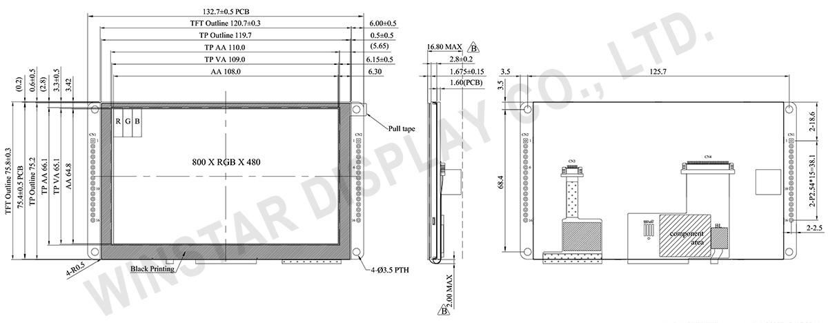
Bom
| Item | Description |
|---|---|
| LCM | WF50FTYAGDNG0#- |
| PCBA | 4 layer FR4, 1.6mm |
SPECIFICATIONS
General Specifications
Mechanical Data
| Item | Standard Value | Unit |
|---|---|---|
| LCD panel | 120.7(W) × 75.8(H) × 4.475 | mm |
| PCB | 132.7(W) × 75.8(H) × 1.6 | mm |
| Housing outline | NA | mm |
General information
| Item | Standard Value | Unit |
|---|---|---|
| Operating voltage | 5 | Vdc |
| Communication Interface | CAN bus differential ± 3.3 | Vpp |
| LCD display size | 5 | inch |
| Dot Matrix | 800 × 3(RGB) × 480 | dot |
| Module dimension | 120.7(W) × 75.8(H) × 4.475 | mm |
| Active area | 108(W) × 64.8 (H) | mm |
| Dot pitch | 0.135(W) × 0.135(H) | mm |
| LCD type | TFT, Normally Black, Transmissive | |
| View Direction | 80/80/80/80 | |
| Aspect Ratio | 16:9 | |
| With /Without TP | With Projected Capacitive Touch Panel (PCAP) | |
| Surface | Glare | |
Absolute Maximum Ratings
| Item | Symbol | Min | Typ | Max | Unit |
|---|---|---|---|---|---|
| Operating Temperature | TOP | -20 | - | +70 | ℃ |
| Storage Temperature | TST | -30 | - | +80 | ℃ |
Electrical Characteristics
Operating conditions| Item | Symbol | Condition | Min | Typ | Max | Unit |
|---|---|---|---|---|---|---|
| Supply Voltage For Analog | VCI | - | 4.75 | 5 | 5.5 | V |
| Interface Operation Voltage | IOVCC | - | 3.234 | 3.30 | 3.367 | V |
| Supply LCM current | ICI(mA) | - | 320 | 350 | - | mA |
LED driving conditions
| Parameter | Symbol | Min. | Typ. | Max. | Unit | Remark |
|---|---|---|---|---|---|---|
| LED current | - | 1.0 | 1.5 | mA | ||
| Power Consumption | - | - | 27 | mW | ||
| LED voltage | VBL+ | - | - | 18 | V | Note 1 |
| LED Life Time | - | 50,000 | - | Hr | Note 2,3,4 |
Note 1 : There are 1 Groups LED

Note 2 : Ta = 25 ℃
Note 3 : Brightness to be decreased to 50% of the initial value
Note 4 : The single LED lamp case
Interface Pin Function
CN1 definition
| Pin | Symbol | Function | Remark |
|---|---|---|---|
| 1 | +5V | Power supply 5V input | Input |
| 2 | GND | Power supply GND input | Input |
| 3 | CAN_High | CAN bus D+ | I/O |
| 4 | CAN_Low | CAN bus D- | I/O |
| 5 | VDD_5V | 5V output for USART interface | Output |
| 6 | USART1_RX | USART RX interface | Reserve |
| 7 | USART1_TX | USART TX interface | Reserve |
| 8 | GND | GND for USART interface | Output |
| 9-16 | NC | Connection | - |
Display Usage
Functional description
Smart Display can be used to display the coordinate, status and data information provided by the connected HOST device. Customers can configure the position coordinates they want to display in normal operation mode.
The Display is designed to be easily connected to a controller network, and to operate with minimum setup or knowledge of the SDO configuration on the controllers.
Splash Screen
The default splash image is shown below.

This product is produced as a generic product. If you require a custom splash image for your application, contact us to discuss.
Acquisition of Displayed Data
The Smart Display can acquire the data that it displays either using the CANopen SDO protocol, or using the CANopen PDO protocol.
On Pre-operational mode, customers can set the coordinates of objects through SDO; On operational mode, customers can send data of objects through PDO.
Configuring the Display
Winstar Smart Display CAN series offers an out-of-the-box CANopen development experience that will lower customers' development costs and speed time-to-market expectations.
The Smart Display can use wide-temperature are designed to support control applications in harsh operating conditions, which designed to be connected to a variety of different situation combinations, such as automotive, marine, power generation and oil-and-gas.
The Smart Display comes with standard UI objects to get customers project off the ground quickly. If customers need custom UI objects support, our engineers are here to help. Send over your contents in PNG/JPG format, we will send over a new set of UI objects within 3~5 working days.
The Smart Display is defined as a slave device, which is controlled by master device via CAN bus command to render display content on the display screen and return touch event data with protocol objects.
Example Screen Layout (Industry application)
Example Layout
The screen layout described in this section is intended to demonstrate the settings of screen items that can be used in a industry application situation.

Example Screen Layout (Vehicle automotive)
Example Layout
The screen layout described in this section is intended to demonstrate the settings of screen items that can be used in a vehicle automotive situation.

Example Screen Layout (Medical application)
Example Layout
The screen layout described in this section is intended to demonstrate the settings of screen items that can be used in a Medical application situation.


