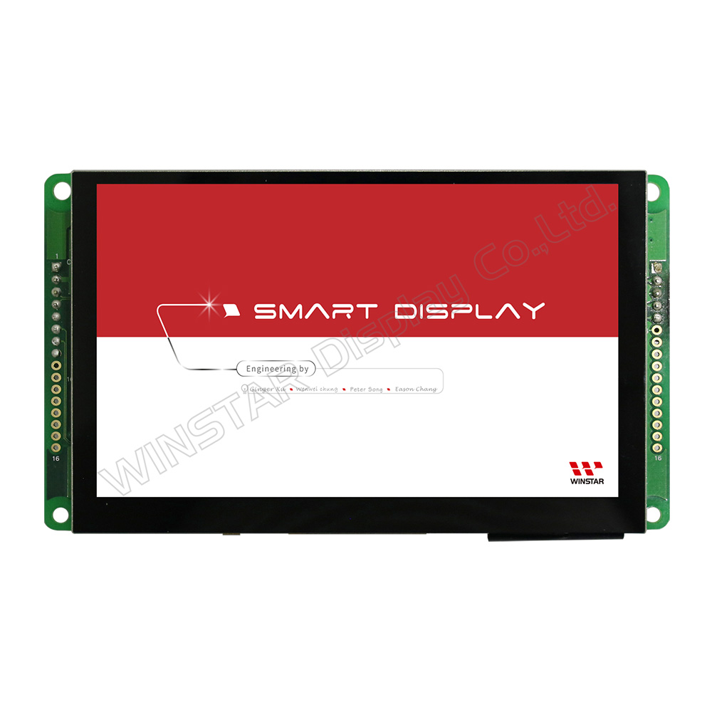
Model No. WL0F00050000FGAAASA00
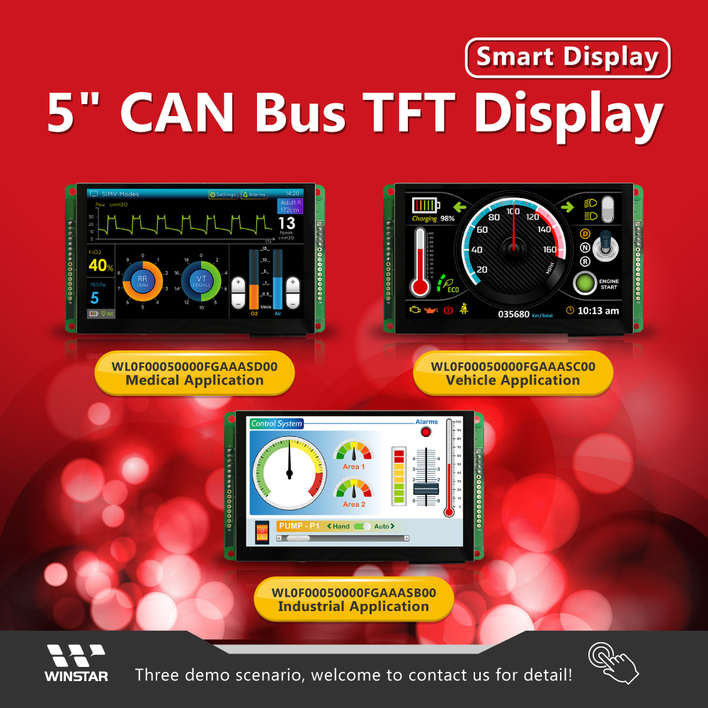
We have three demo scenario as below.
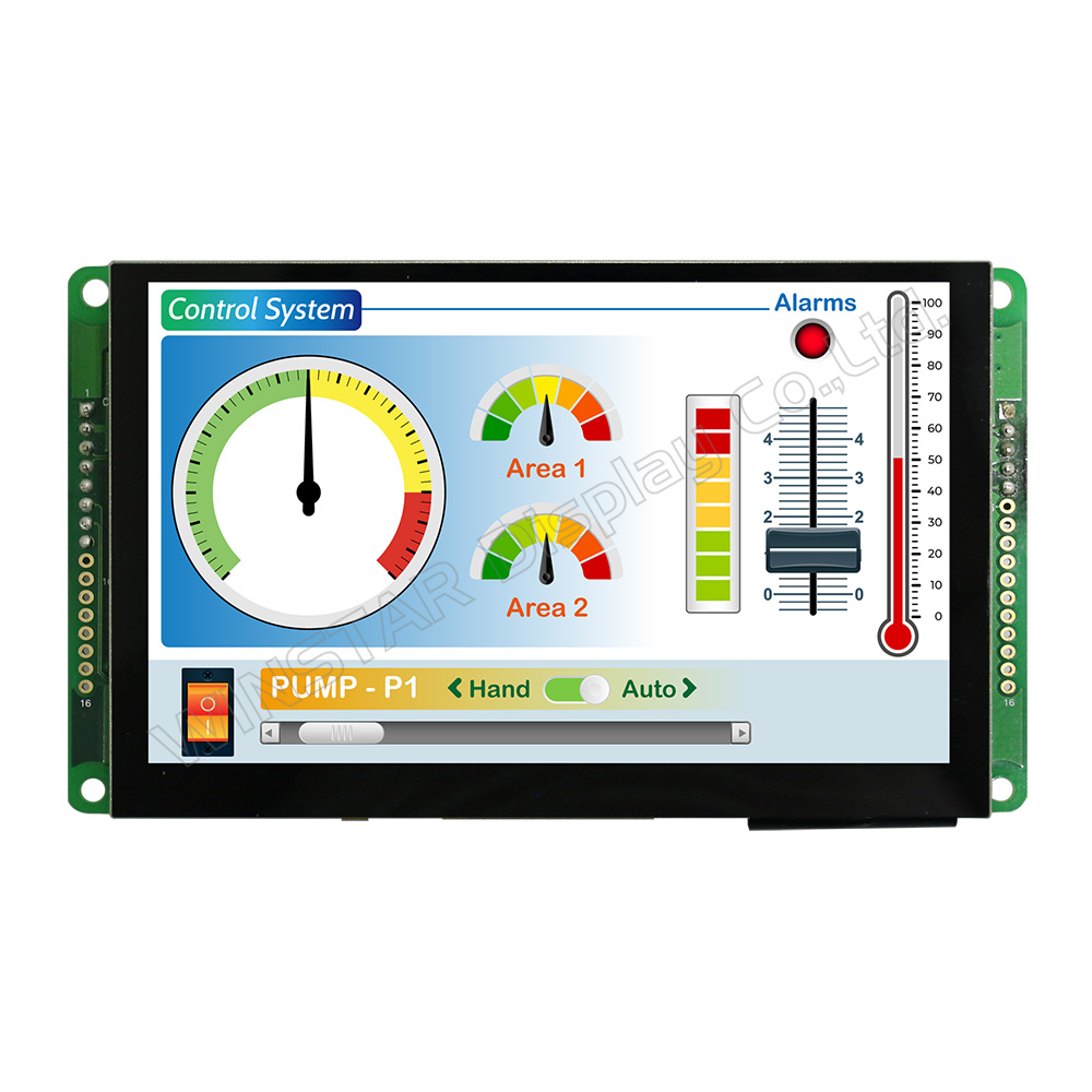
WL0F00050000FGAAASB00 (Industrial Application)
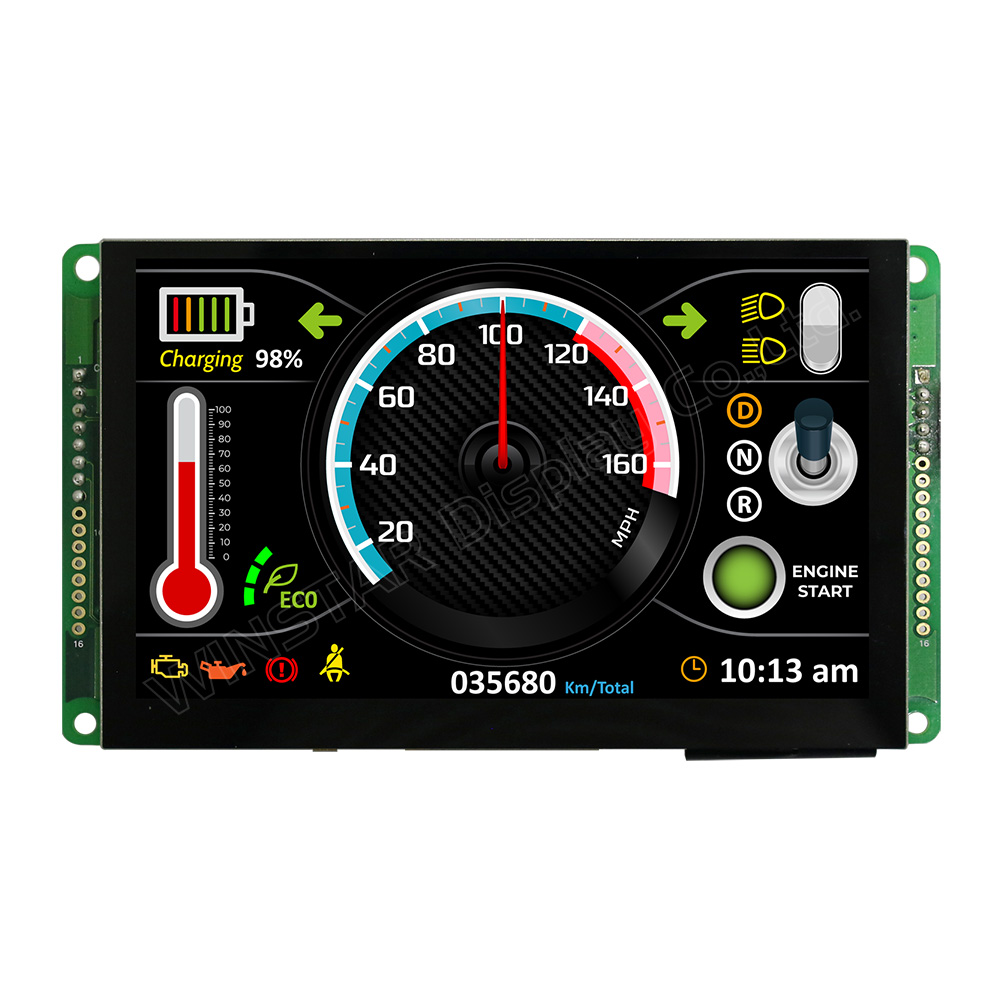
WL0F00050000FGAAASC00 (Vehicle Application)
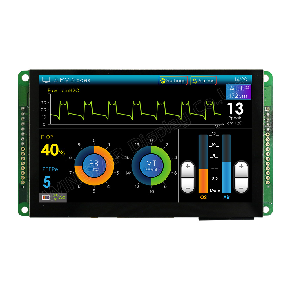
WL0F00050000FGAAASD00 (Medical Application)
►TFT Tamanho: 5 polegadas
►TFT Resolução: 800×480 pontos
►TFT Direção de exibição: IPS
►TFT Tela de Toque: Com painel de toque capacitivo
►TFT P/N: WF50FTYAGDNG0#
►Communication Interface: CAN bus
DRAWING
Bom
| Item | Description |
|---|---|
| LCM | WF50FTYAGDNG0#- |
| PCBA | 4 layer FR4, 1.6mm |
SPECIFICATIONS
General Specifications
Mechanical Data
| Item | Standard Value | Unit |
|---|---|---|
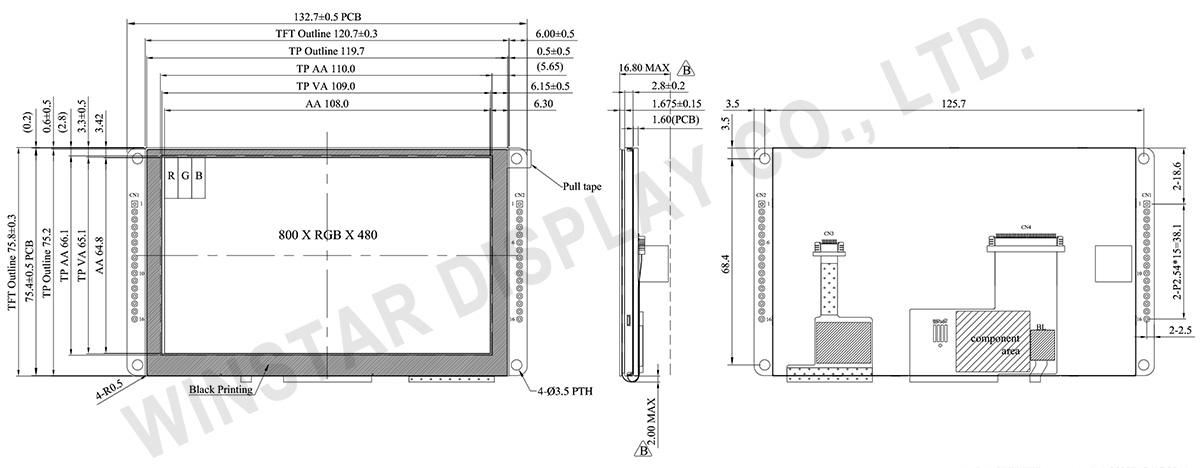
| LCD panel | 120.7(W) × 75.8(H) × 4.475 | mm |
| PCB | 132.7(W) × 75.8(H) × 1.6 | mm |
| Housing outline | NA | mm |
General information
| Item | Standard Value | Unit |
|---|---|---|
| Operating voltage | 5 | Vdc |
| Communication Interface | CAN bus differential ± 3.3 | Vpp |
| LCD display size | 5 | inch |
| Dot Matrix | 800 × 3(RGB) × 480 | dot |
| Module dimension | 120.7(W) × 75.8(H) × 4.475 | mm |
| Active area | 108(W) × 64.8 (H) | mm |
| Dot pitch | 0.135(W) × 0.135(H) | mm |
| LCD type | TFT, Normally Black, Transmissive | |
| View Direction | 80/80/80/80 | |
| Aspect Ratio | 16:9 | |
| With /Without TP | With Projected Capacitive Touch Panel (PCAP) | |
| Surface | Glare | |
Absolute Maximum Ratings
| Item | Symbol | Min | Typ | Max | Unit |
|---|---|---|---|---|---|
| Operating Temperature | TOP | -20 | - | +70 | ℃ |
| Storage Temperature | TST | -30 | - | +80 | ℃ |
Electrical Characteristics
Operating conditions| Item | Symbol | Condition | Min | Typ | Max | Unit |
|---|---|---|---|---|---|---|
| Supply Voltage For Analog | VCI | - | 4.75 | 5 | 5.5 | V |
| Interface Operation Voltage | IOVCC | - | 3.234 | 3.30 | 3.367 | V |
| Supply LCM current | ICI(mA) | - | 320 | 350 | - | mA |
LED driving conditions
| Parameter | Symbol | Min. | Typ. | Max. | Unit | Remark |
|---|---|---|---|---|---|---|
| LED current | - | 1.0 | 1.5 | mA | ||
| Power Consumption | - | - | 27 | mW | ||
| LED voltage | VBL+ | - | - | 18 | V | Note 1 |
| LED Life Time | - | 50,000 | - | Hr | Note 2,3,4 |
Note 1 : There are 1 Groups LED

Note 2 : Ta = 25 ℃
Note 3 : Brightness to be decreased to 50% of the initial value
Note 4 : The single LED lamp case
Interface Pin Function
CN1 definition
| Pin | Symbol | Function | Remark |
|---|---|---|---|
| 1 | +5V | Power supply 5V input | Input |
| 2 | GND | Power supply GND input | Input |
| 3 | CAN_High | CAN bus D+ | I/O |
| 4 | CAN_Low | CAN bus D- | I/O |
| 5 | VDD_5V | 5V output for USART interface | Output |
| 6 | USART1_RX | USART RX interface | Reserve |
| 7 | USART1_TX | USART TX interface | Reserve |
| 8 | GND | GND for USART interface | Output |
| 9-16 | NC | Connection | - |