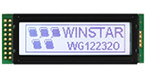
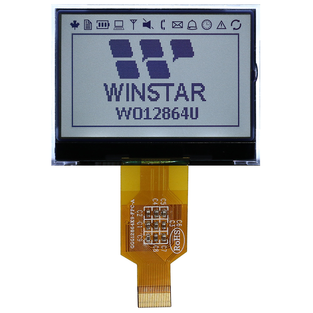
Model No. WO12864U
►LCD COG 128x64
►LCD Gráfico
►Controlador ST7565P integrado
►Alimentação 3,3V
►1/64 duty cycle, 1/9 bias
►Interface : 6800/8080/SPI
DESCRIPTION
DRAWING
SPECIFICATIONS
Interface Pin Function
| Pin No. | Symbol | I/O | Description | ||||||||||||
|---|---|---|---|---|---|---|---|---|---|---|---|---|---|---|---|
| 1 | VDD | _ | Power supply pin for logic. | ||||||||||||
| 2 | VSS | _ | Ground pin, connected to 0V | ||||||||||||
| 3 | /CS1 | I | Chip select input pin. Interface access is enabled when CS1B is "L" and CB2 is "H" . When chip is on-active (CS1B="H" or CS2="L"), D[7:0] pins are high impedance. | ||||||||||||
| 4 | CS2 | ||||||||||||||
| 5 | /RES | I | Hardware reset input pin. When RSTB is "L", internal initialization is executed and the internal registers will be initialized. | ||||||||||||
| 6 | A0 | I | It determines whether the access is related to data or command. A0=“H”: Indicates that signals on D[7:0] are display data. A0=“L”: Indicates that signals on D[7:0] are command. |
||||||||||||
| 7 | R/W | I | Read/Write execution control pin. When PSB is "H",
RWR is not used in serial interface and should fix to "H" by VDD. |
||||||||||||
| 8 | E | I | Read/Write execution control pin. When PSB is "H",
ERD is not used in serial interface and should fix to "H" by VDD. |
||||||||||||
| 9-16 | D0-D7 | I/O | Data bus line | ||||||||||||
| 17 | C86 | I | C86 selects the microprocessor type in parallel interface mode.
Please refer to “APPLICATION NOTES” and “Microprocessor Interface” (Section 6) for detailed connection of the selected interface. |
||||||||||||
| 18 | P/S | I | PSB selects the interface type: Serial or Parallel. |
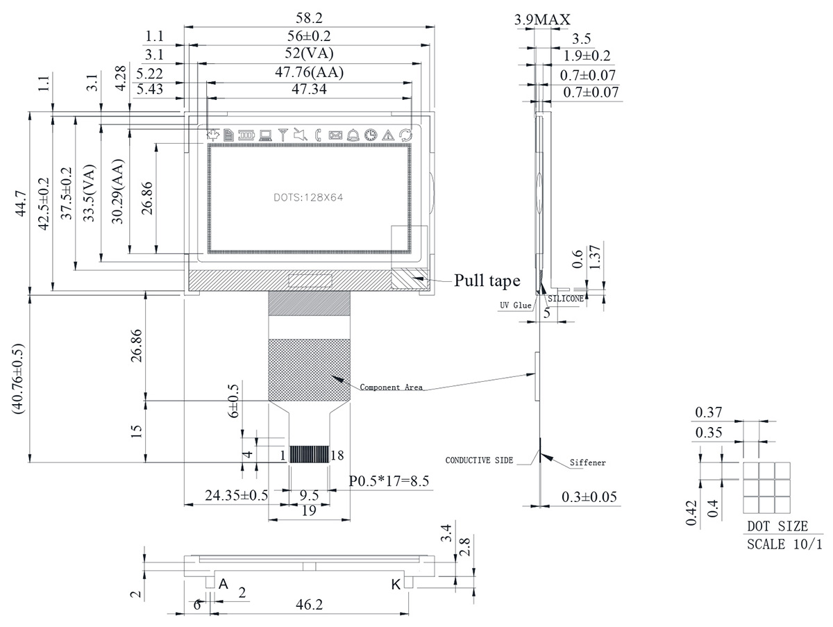
General Specification
| Item | Dimension | Unit |
|---|---|---|
| Number of dots | 128 × 64 | - |
| Module dimension | 58.2 × 44.7 × 3.9(MAX) | mm |
| View area | 52.0 × 33.5 | mm |
| Active area | 47.76 × 30.29 | mm |
| Dot size | 0.40 × 0.35 | mm |
| Dot pitch | 0.42 × 0.37 | mm |
| Duty | 1/64 | |
| Backlight Type | LED | |
| IC | ST7565P | |
Absolute Maximum Ratings
| Item | Symbol | Min | Typ | Max | Unit |
|---|---|---|---|---|---|
| Operating Temperature | TOP | -20 | - | +70 | ℃ |
| Storage Temperature | TST | -30 | - | +80 | ℃ |
| Power Supply Voltage | VDD | -0.3 | - | 3.6 | V |
| Power supply voltage (VDD standard) | V0, VOUT | -0.3 | - | 14.5 | V |
| Power supply voltage (VDD standard) | V1, V2, V3, V4 | -0.3 | - | V0+0.3 | V |
Electrical Characteristics
| Item | Symbol | Condition | Min. | Typ. | Max. | Unit |
|---|---|---|---|---|---|---|
| Supply Voltage For Logic | VDD-VSS | - | 3.0 | - | 3.3 | V |
| Supply Voltage For LCD | VOP | Ta=-20℃ Ta=25℃ Ta=70℃ |
- 8.3 - |
- 8.5 - |
- 8.7 - |
V V V |
| Input High Volt. | VIH | - | 0.8VDD | - | VDD | V |
| Input Low Volt. | VIL | - | VSS | - | 0.2VDD | V |
| Output High Volt. | VOH | - | 0.8VDD | - | VDD | V |
| Output Low Volt. | VOL | - | VDD | - | 0.2VDD | V |
| Supply Current | IDD | VDD=3.3V | - | 1 | 2 | mA |