


Punktmatrix Display 240x128
Modellnummer WO240128B
►Punktmatrix Display
►COG LCD
►Grafik LCD
►240 x 128 dots
►Integrierter Controller ST7586S
►3,3-V-Stromversorgung
►1/128 duty cycle
►Schnittstelle : 6800/8080/SPI
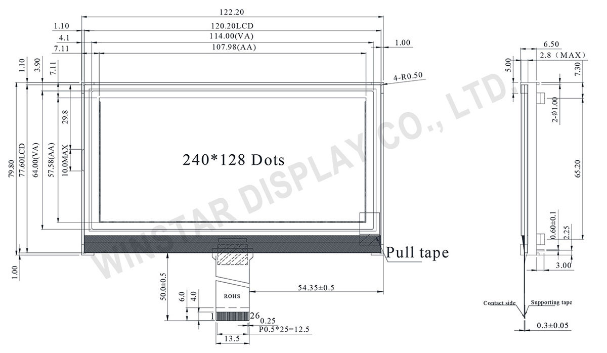
Zeichnung
Technische Daten
Schnittstelle Pin-Funktion
| Pin No. | Symbol | Beschreibung |
|---|---|---|
| 1 | ESD GND | Electro-Static discharge |
| 2 | VG | VG is the power of SEG-drivers |
| 3 | XV0 | Negative operating voltage of COM-drivers |
| 4 | V0 | Positive operating voltage of COM-drivers |
| 5 | VM | VM is the non-select voltage level of COM-drivers |
| 6 | VDDA | Power supply |
| 7 | VSS | Ground |
| 8 | VD1 | Digital power source selection |
| 9 | VDDI | VDD1 is the power of interface I/O circuit |
| 10 | CSB | Chip select input pin CSB=“L”: This chip is selected and the MPU interface is active CSB=“H”: This chip is not selected and the MPU interface is disabled (D[7:0] are high impedance) |
| 11 12 13 |
IF3 IF2 IF1 |
These pins select interface operation mode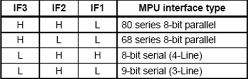 Note: Refer to “Interface Selection” for detailed information |
| 14 | RSTB | Reset input pin. When RSTB is “L”, internal initialization procedure is executed |
| 15 | /RD(E) | Read / Write execution control pin. (This pin is only used in parallelinterface)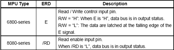 This pin is not used in serial interfaces and should be connected to VDD1 |
| 16~23 | D7~D0 | The bi-directional data bus of the MPU interface. When CSB is “H”, they are high impedance If using serial interface: D0 is the SDA signal in 4-Line & 3-Line interface D1 is the A0 signal in 4-Line interface |
| 24 | /WR/(R/W) | Read / Write execution control pin. (This pin is only used in parallel interface)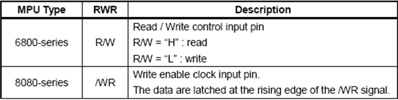 This pin is not used in serial interfaces and should be connected to VDD1 |
| 25 | A0(SCL) | The function of this pin is different in parallel and serial interface In parallel interface: A0 is register selection input A0 = "H": inputs on data bus are display data A0 = "L": inputs on data bus are command In serial interface: this pad will be used as SCL (serial-clock) input |
| 26 | ESD GND | Electro-Static discharge |
mechanische Daten
| Artikel | Standardwert | Einheit |
|---|---|---|
| Punktmatrix | 240 x 128 | - |
| Abmaße der modul | 122,2 x 79,8 x 6,5 | mm |
| Anzeigebereich | 114,0 x 64,0 | mm |
| Aktiver Bereich | 107,98 x 57,58 | mm |
| Punktgröße | 0,43 x 0,43 | mm |
| Punktabstand | 0,45 x 0,45 | mm |
| Drive Method | 1/128Duty,1/12Bias | |
| Hintergrundbeleuchtung Typ | LED | |
| IC | ST7586S | |
absolute Grenzwerte
| Artikel | Symbol | Mindestwert | typischer Wert | Maximalwert | Einheit |
|---|---|---|---|---|---|
| Betriebstemperatur | TOP | -20 | - | +70 | ℃ |
| Lagertemperatur | TST | -30 | - | +80 | ℃ |
| Digital Power Supply Voltage | VDDI | -0,3 | - | 3,6 | V |
| Analog Power supply voltage | VDDA | -0,3 | - | 3,6 | V |
| LCD Power supply voltage | V0-XV0 | -0,3 | - | 19 | V |
| LCD Power supply voltage | VG | -0,3 | - | 5,5 | V |
elektrische Eigenschaften
| Artikel | Symbol | Bedingung | Mindestwert | typischer Wert | Maximalwert | Einheit |
|---|---|---|---|---|---|---|
| Supply Voltage For Logic | VDD-VSS | - | 3,0 | 3,3 | 3,6 | V |
| Supply Voltage For LCM | VOP | Ta=-20℃ Ta=25℃ Ta=+70℃ |
- 14,8 - |
- 15,0 - |
- 15,2 - |
V V V |
| Input High Volt. | VIH | - | 0.7VDD | - | VDD | V |
| Input Low Volt. | VIL | - | Vss | - | 0,3 VDD | V |
| Output High Volt. | VOH | - | 0,8 VDD | - | VDD | V |
| Output Low Volt. | VOL | - | Vss | - | 0,2VDD | V |
| Supply Current | IDD | VDD=3,3V | - | - | 2,0 | mA |


