Interface
LCM PIN Definition
| Pin |
Symbol |
Function |
| 1 |
GND |
Power Ground |
| 2 |
GND |
Power Ground |
| 3 |
NC |
Not Connect |
| 4 |
Vcc |
Power Supply for Digital Circuit |
| 5 |
Vcc |
Power Supply for Digital Circuit |
| 6 |
Vcc |
Power Supply for Digital Circuit |
| 7 |
Vcc |
Power Supply for Digital Circuit |
| 8 |
NC |
Not Connect |
| 9 |
DE |
Data Enable |
| 10 |
GND |
Power Ground |
| 11 |
GND |
Power Ground |
| 12 |
GND |
Power Ground |
| 13 |
B5 |
Blue Data 5 (MSB) |
| 14 |
B4 |
Blue Data 4 |
| 15 |
B3 |
Blue Data 3 |
| 16 |
GND |
Power Ground |
| 17 |
B2 |
Blue Data 2 |
| 18 |
B1 |
Blue Data 1 |
| 19 |
B0 |
Blue Data 0 (LSB) |
| 20 |
GND |
Power Ground |
| 21 |
G5 |
Green Data 5 (MSB) |
| 22 |
G4 |
Green Data 4 |
| 23 |
G3 |
Green Data 3 |
| 24 |
GND |
Power Ground |
| 25 |
G2 |
Green Data 2 |
| 26 |
G1 |
Green Data 1 |
| 27 |
G0 |
Green Data 0(LSB) |
| 28 |
GND |
Power Ground |
| 29 |
R5 |
Red Data 5 (MSB) |
| 30 |
R4 |
Red Data 4 |
| 31 |
R3 |
Red Data 3 |
| 32 |
GND |
Power Ground |
| 33 |
R2 |
Red Data 2 |
| 34 |
R1 |
Red Data 1 |
| 35 |
R0 |
Red Data 0(LSB) |
| 36 |
GND |
Power Ground |
| 37 |
GND |
Power Ground |
| 38 |
DCLK |
Clock Signals ; Latch Data at the Falling Edge |
| 39 |
GND |
Power Ground |
| 40 |
GND |
Power Ground |
Backlight Driving Part
| Pin No. |
Symbol |
Description |
| 1 |
VLED+ |
Red, LED_ Anode |
| 2 |
VLED- |
White, LED_ Cathode |
CTP PIN Definition
| Pin |
Symbol |
Function |
| 1 |
VSS |
Ground for analog circuit |
| 2 |
VDDT |
Power Supply : +3.3V |
| 3 |
SCL |
I2C clock input |
| 4 |
NC |
No connect |
| 5 |
SDA |
I2C data input and output |
| 6 |
NC |
No connect |
| 7 |
/RST |
External Reset, Low is active |
| 8 |
NC |
No connect |
| 9 |
/INT |
External interrupt to the host |
| 10 |
VSS |
Ground for analog circuit |
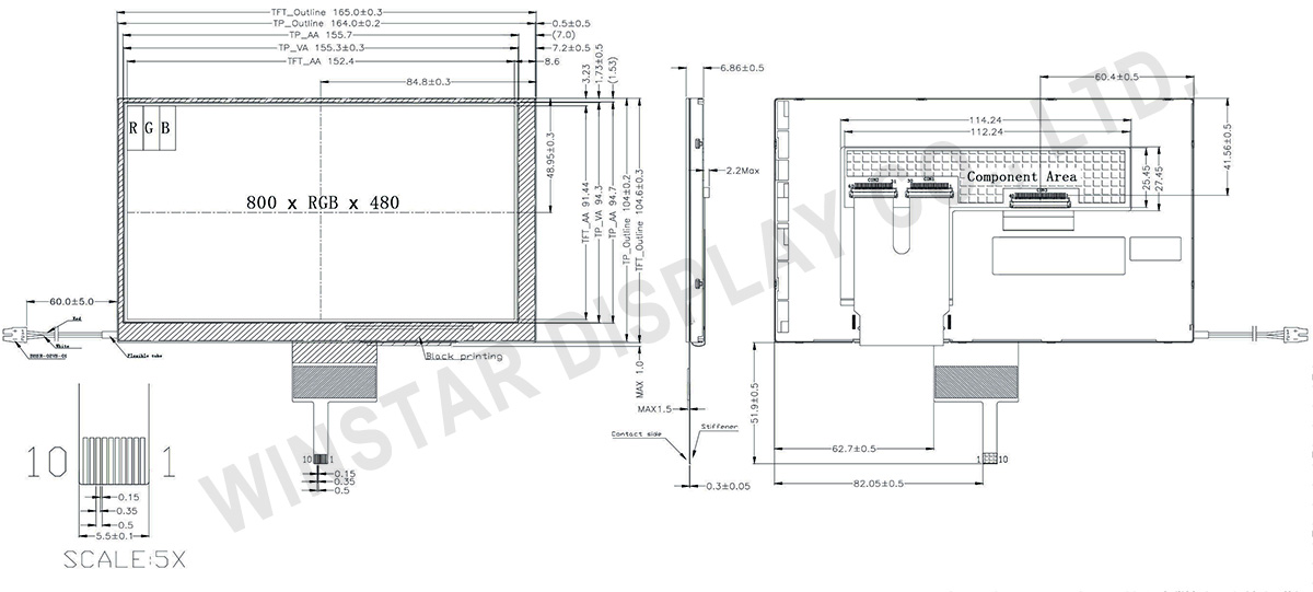
General Specifications
| Item |
Dimension |
Unit |
| Size |
7.0 |
inch |
| Dot Matrix |
800 × RGB × 480 (TFT) |
dots |
| Module dimension |
165 × 104.6 × 6.86 |
mm |
| Active area |
152.4 × 91.44 |
mm |
| Dot pitch |
0.0635 × 0.1905 |
mm |
| LCD type |
TFT, Normally White, Transmissive |
| TFT Interface |
18-bit RGB |
| View Direction |
12 o'clock |
| Gray Scale Inversion Direction |
6 o'clock |
| Aspect Ratio |
16:9 |
| PCAP FW Version |
0x13 |
| PCAP Interface |
I2C |
| PCAP IC |
FT5426 Or Equal |
| Backlight Type |
LED, Normally White |
| Touch Screen |
Projected capacitive touch screen (PCAP) |
| Surface |
Glare |
Absolute Maximum Ratings
| Item |
Symbol |
Min |
Typ |
Max |
Unit |
| Operating Temperature |
TOP |
-20 |
- |
+70 |
℃ |
| Storage Temperature |
TST |
-30 |
- |
+80 |
℃ |
Electrical Characteristics
Absolute Maximum Ratings(GND=0V)
| Item |
Symbol |
Min |
Typ |
Max |
Unit |
| Power Voltage |
Vcc |
-0.3 |
- |
6 |
V |
| Input Signal Voltage |
Vi |
-0.3 |
- |
Vcc+0.3 |
V |
Recommended Operation condition (GND=0V,Ta=25℃)
| Item |
Symbol |
Min |
Typ |
Max |
Unit |
| Power Supply Voltage |
Vcc |
3.0 |
3.3 |
3.6 |
V |
| Supply current For LCM |
Icc |
- |
160 |
270 |
mA |
| Power Consumption |
- |
- |
530 |
970 |
mW |
| Supply Voltage For CTP |
VDDT |
2.8 |
- |
3.3 |
V |
| Input logic Voltage |
High Level |
VIH |
0.7Vcc |
- |
Vcc |
V |
| Low Level |
VIL |
0 |
- |
0.3Vcc |
Search keyword: tft 7, tft 7", 7 tft lcd, 7" tft lcd, 7 inch tft lcd, tft lcd 7, 7 tft display, 7" tft display, 7 inch tft display, tft display 7, tft display 7", 7.0 tft lcd